Ryan and Rhea have decided she needs a new boom box to play her Israeli folk dance music while teaching. Her old boom box no longer works with her phone. I looked online for box ideas and found one design that seemed unique and doable. Unfortunately, it only accommodates two speakers and Ryan has determined that four are needed. He is in charge of the electronics. I will build the box.
The design spotted on the web is essentially a rectangular box with two speakers adjacent in front. Its uniqueness is the rounded ends of the box. It is made from sheets of plywood all cut from the same template. The sheets are layered together to make the box. Certainly seems doable, though routing with a template will be new for me. The challenge is where to put the additional two speakers. I don't think two can be added to the top unless the top is raised well above the front mounted speakers. An alternative that struck my fancy is an angled top tilting up from front to back. This would provide the needed room and not throw off the look of the front face. The challenge is construction. Each layer from front to back would need to raise the top relative to the previous layer. So each layer requires a new template. Once glued up the top would have a series of ridges. These would need to be removed in some fashion. Two attempted sketches are below.
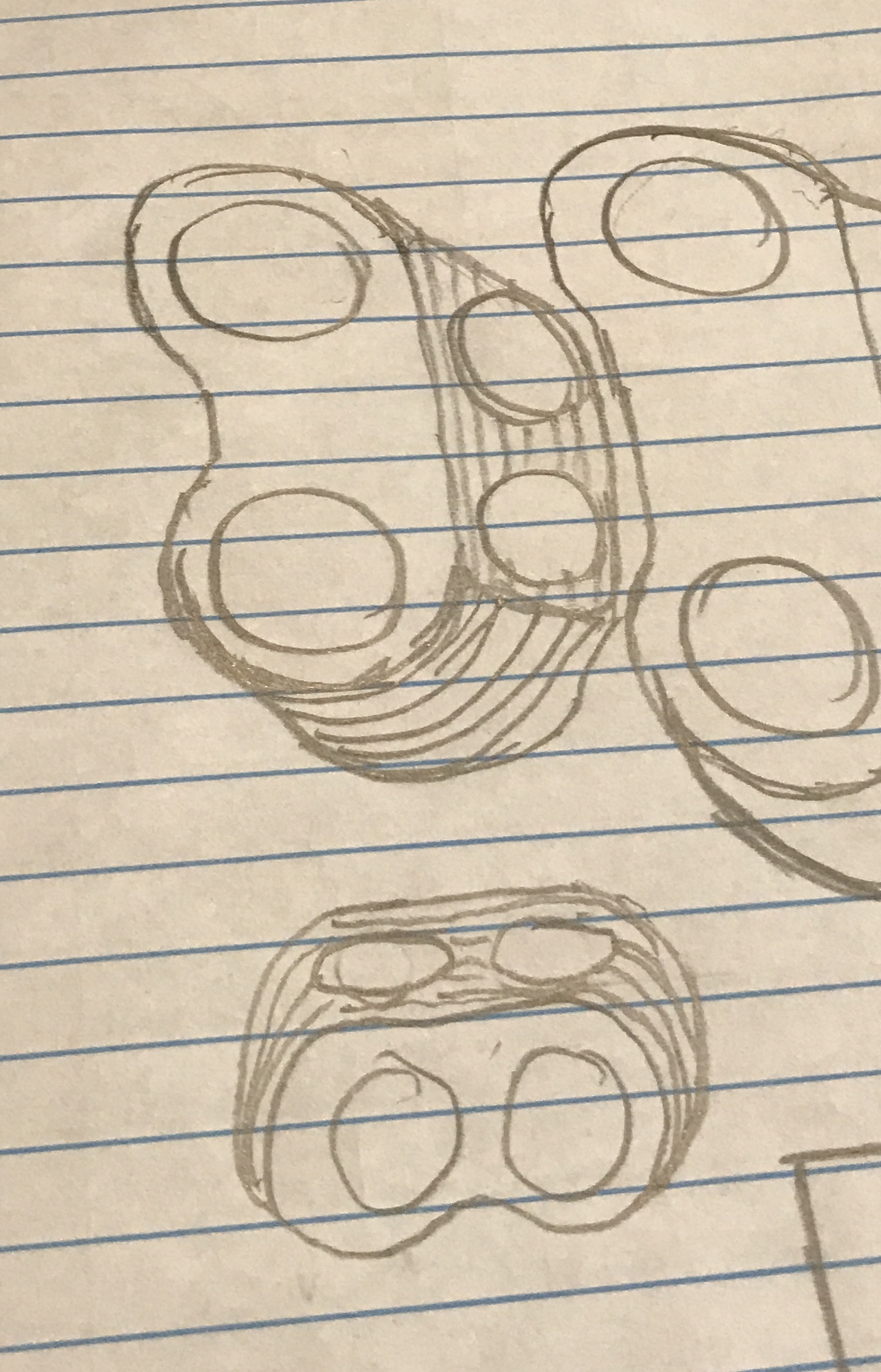
The second idea that occurred to me at 3 am was a dodecahedron half, a hemi-dodecahedron. This shape would have five full pentagonal faces. One facing forward and pointed a little toward the ground with a flat side on the bottom parallel to the ground (face F in the sketch below). Four pentagonal faces would flank this face, two above the forward facing pentagon and two to the sides. These four faces would hold the speakers. The front face could be decorated or hold any switches. The back would be flat and connected to the five faces by sliced off pentagonal faces. A rough sketch is shown below.
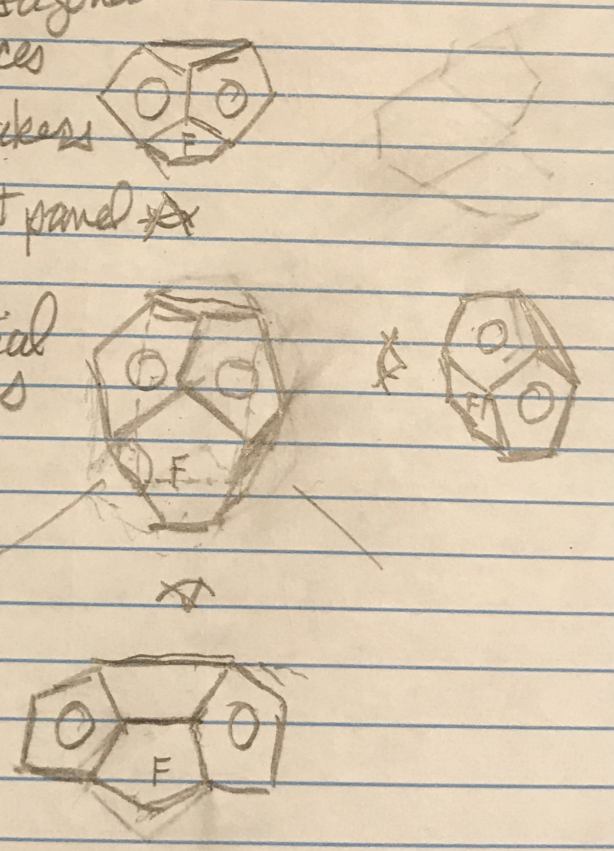
The bolt circle diameter on the chosen speakers is 5". The speaker extends beyond the bolt circle, so the minimum size to consider is ~6". This must fit within the four pentagons. To find the largest square that will fit within a given pentagon, the inradius, r, is used. If t is the length of a side then r = 0.6882 X t. The diagonal of the square is 2r = 1.3764 X t. The length of the side of a square is s = r√2. Consequently, t = s / (√2 X 0.6882). The side of the smallest pentagon that contains a 6" square is 6.165". The pentagons need to be larger than this (7"?), because the pentagon edges are not square, but angle in producing a smaller pentagon. The hemi-dodecahedron would stand almost a foot tall.
Ryan said that a 3" or 3.5" speaker would also work. The 3" speaker has a bolt circle of 3.75". This leads to a 4.75" square for the speaker. The corresponding containing pentagon is 4.88", so maybe a 5 1/2" pentagon might work. This would yield a more acceptable size for the overall box and keep the weight down.
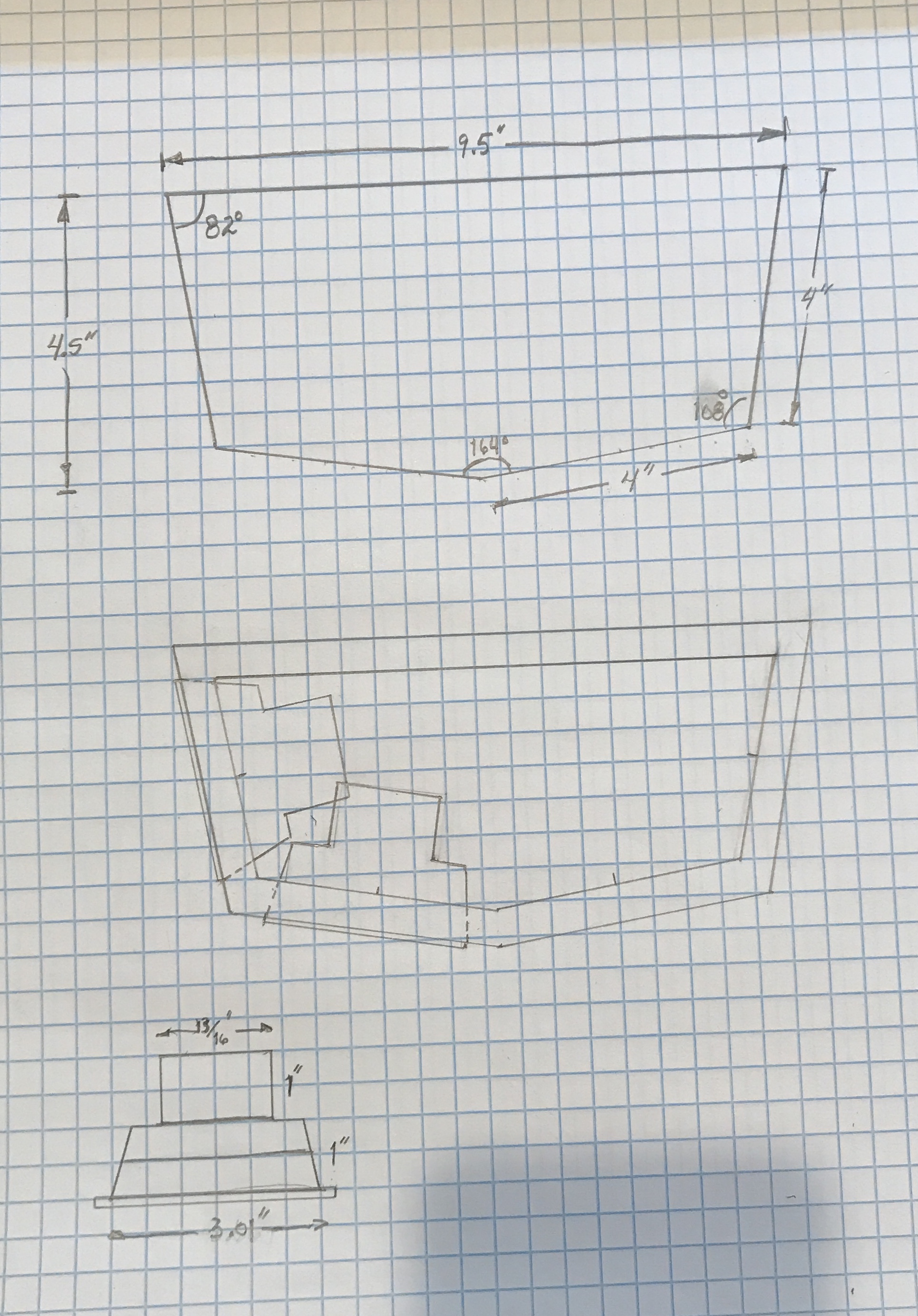
Ryan had a number of legitimate concerns about the hemi-dodecahedron. He suggested a rectangle with the front and three sides replaced with four angled panels forming a pentagon: flat bottom and top. The four speakers would all be arrayed to point mostly forward. He also suggested a 3.5" speaker, whose bolt circle is 93 mm, 3.66". I like the idea for its simplicity. I made more detailed drawings and found a problem with the design. The 4" sides do not leave sufficient room for the extensions of the speakers behind the panels. The side and front speakers bump, if not overlap. Longer panels will be needed, 4 1/2" to 5" should be sufficient.
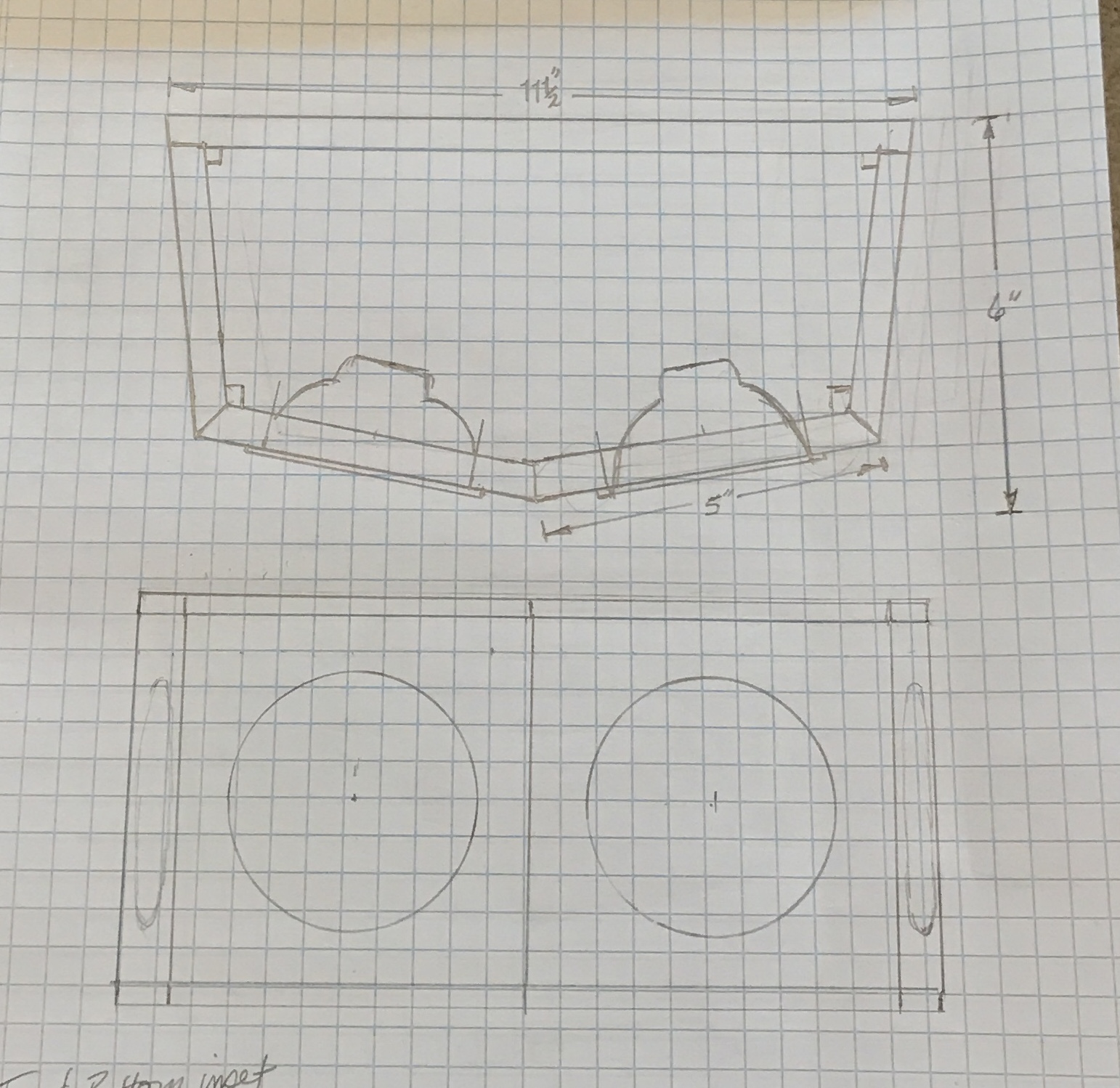
Ryan provided specs on a new 3 1/2" speaker. There is no longer a problem with speakers bumping into one another. One problem remains and that is the corner clearance. In the back corners the speakers run right into the back wall. Moving to 4 1/2" or 5" is a necessity for these speakers. The photo below shows the plan with 5" sides and 5" height minus the top and bottom, which will be set in with rabbets. Menards sells red oak, poplar and aspen in 1/2" X 8" (7/16" X 7 1/4"). Approximately 60" is required.
The current plan is to glue all of the joints and reinforce the side joints with inserts as shown above. An outstanding question is whether access to the box interior is required. If so, either the top or back could be attached by screwing instead of gluing.
With most of the questions resolved the wood, 1/2" X 5 1/2" X 4' poplar(X2), was purchased at Menards. The angles on the drawing above were carefully measured, realizing that the total of the angles should be 540°. The back two angles are 82°. The outside corners on the front are both 108° and the central angle on the front is 160°. The table saw blade will be set to 54° and 80° for the front three angles, respectively and 82° for the back corners.
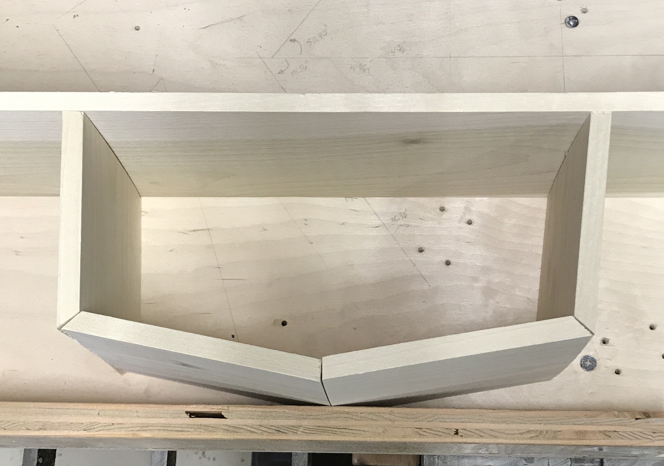
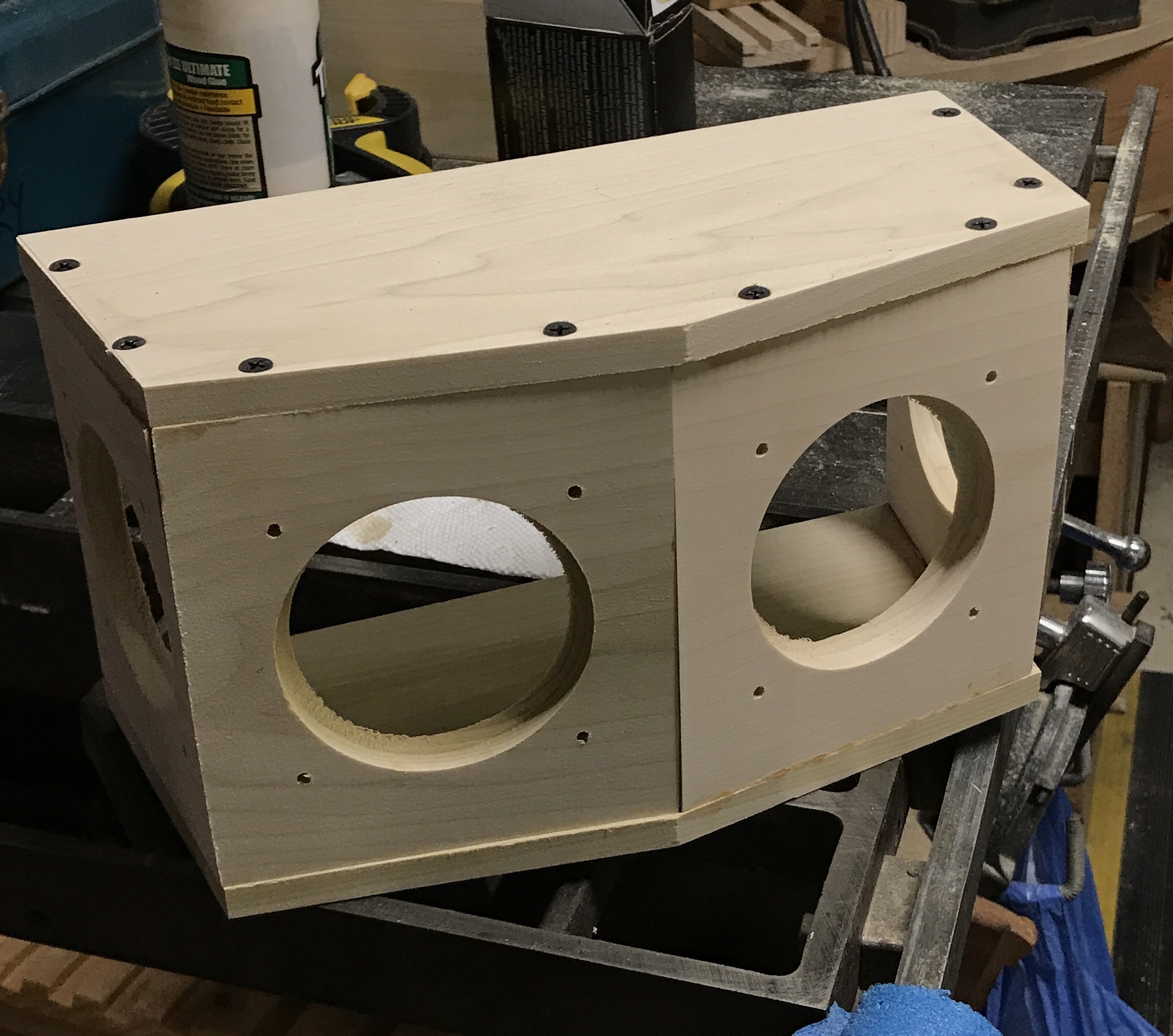
The plan of cutting is as follows: first, two ends of the wood will be cut at 82°. Secondly, these pieces will be cut off with 54° angles. Third, a second set of 54° angles will be cut on these new ends. Fourth, these two faces will be cut off at 80°. When the blade is at 82° two reinforcing strips will be cut. Similarly, two reinforcing strips will be cut with the blade at 54° and one when the blade is at 80°. The top and the bottom will be cut and after cutting to shape will be attached with screws and glue. The back will extend above and below the sides. It needs to be wider than the nominal 5 1/2", so will be made of two pieces. It will be attached only with screws. (Reinforcing the back joints may not be necessary.) Of course, before putting the box together the speaker holes need to be cut out.
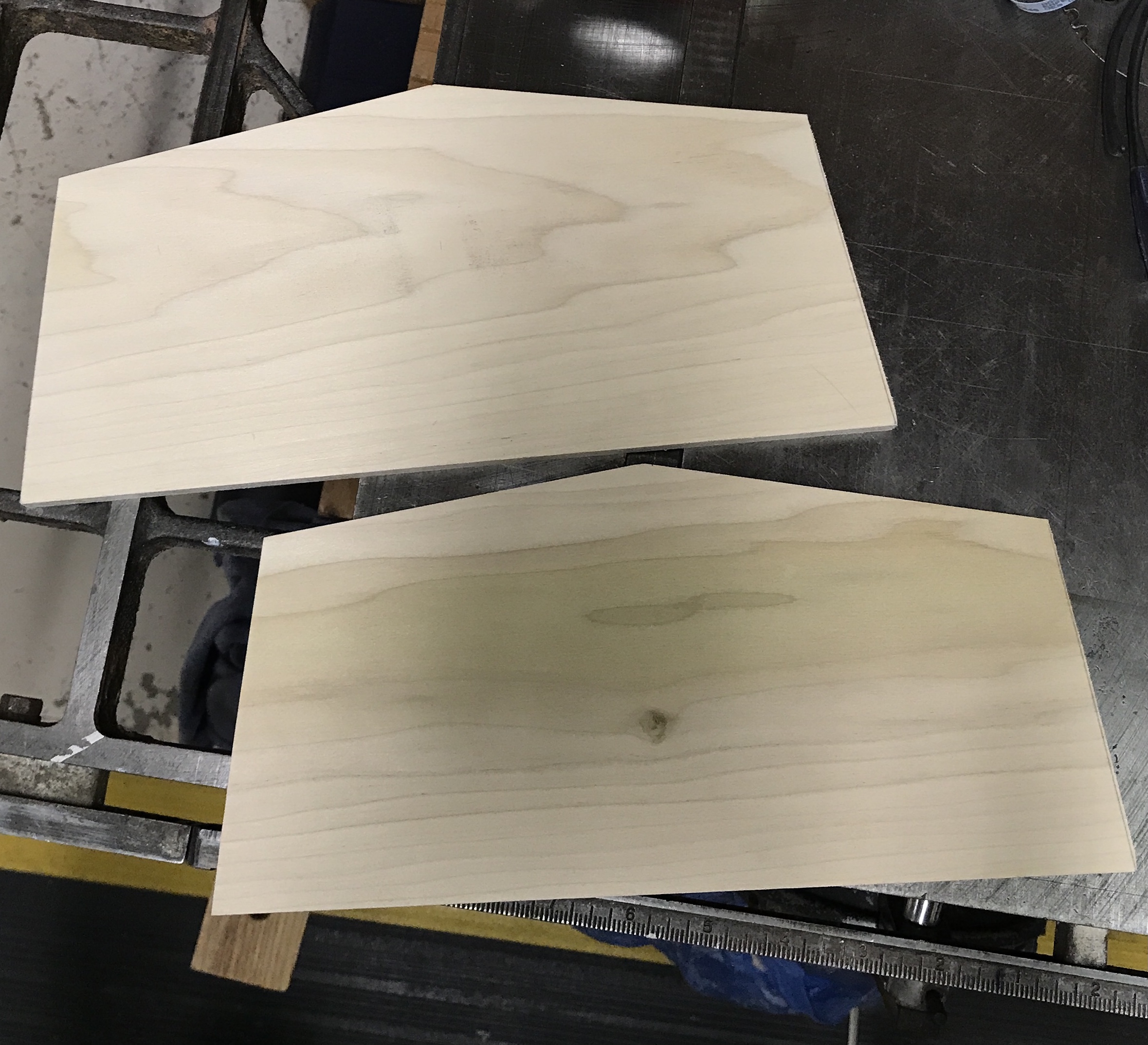
The two front pieces are 5 1/8" long and the two side pieces are 4 1/2" long. All of the sides were cut as described above. The top and bottom were cut to 11 1/2" long. Then the angles were cut using the miter. The miter was set by matching lines drawn on the top and bottom to a line drawn on the table from the blade. The only thing not done was making the final reinforcing strip for the front angle. I am not sure how to make this piece. The first photo shows the pieces arranged to check the angles. The second photo shows the top and bottom cut to fit the angles produced by the sides.
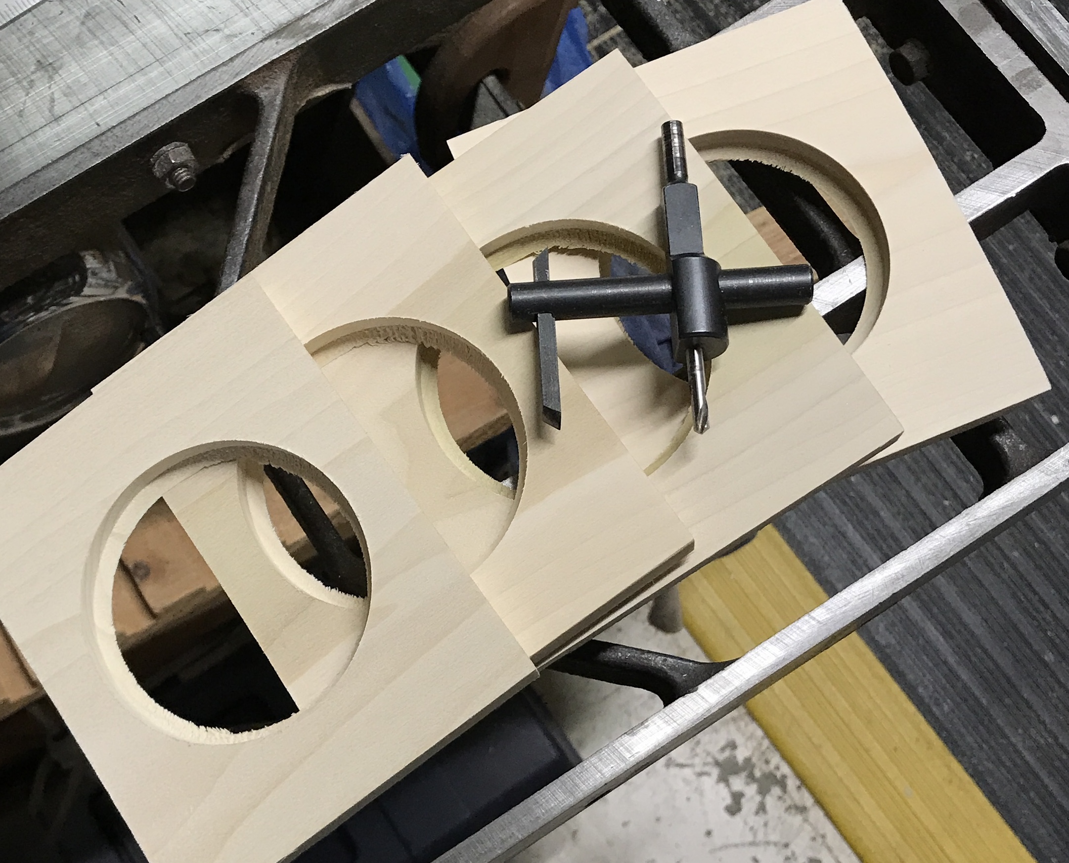
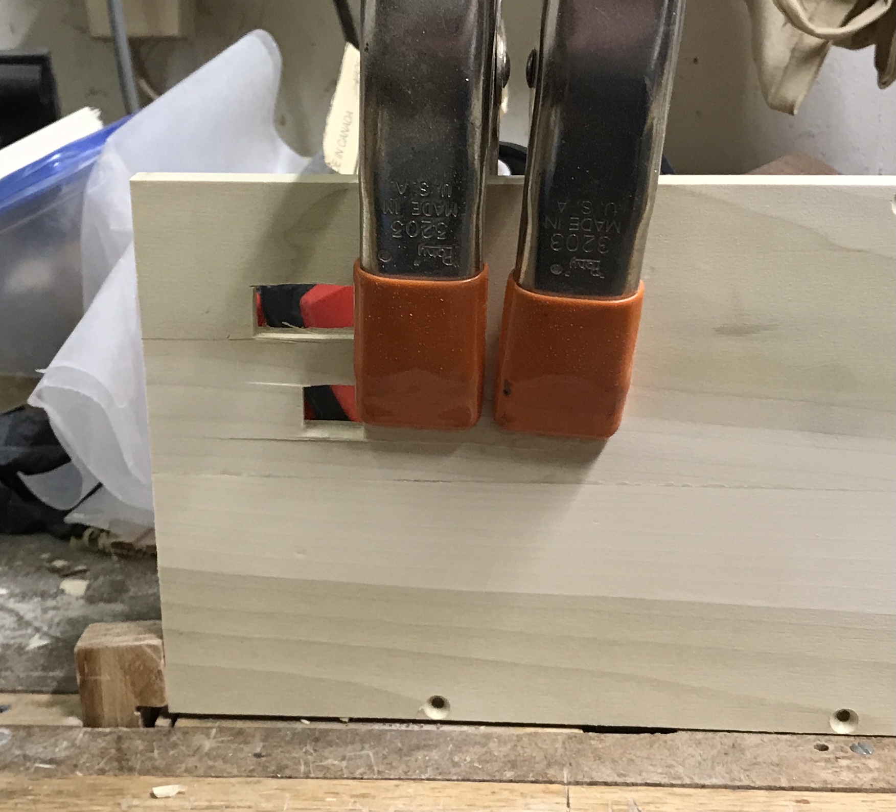
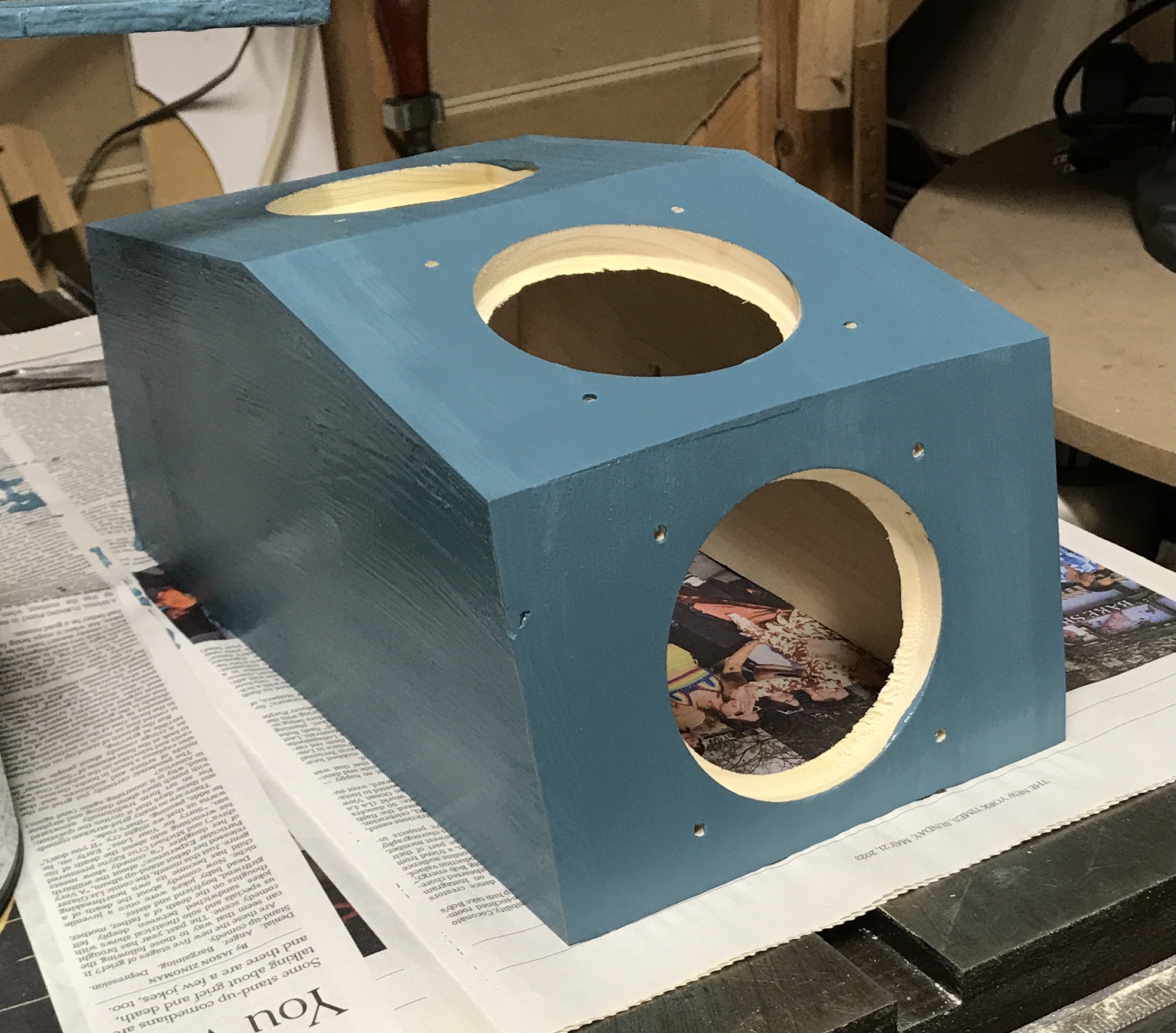
The electronics were ordered and arrived. The stated hole size for the speakers is 83.5 mm. A hole cutter was set to 1.64" with a caliper. The large drill press was used as it is now slower than the smaller. The four faces were marked and punched for the center holes. A fence was clamped to the table. The piece was held tight to the fence, but it was not the sturdiest fence. The hole cutting well nevertheless. The four holes and the hole cutter are shown below. The holes were not completed as the cutter was set for cutting wheels. It doesn't matter as the speakers are a good fit.
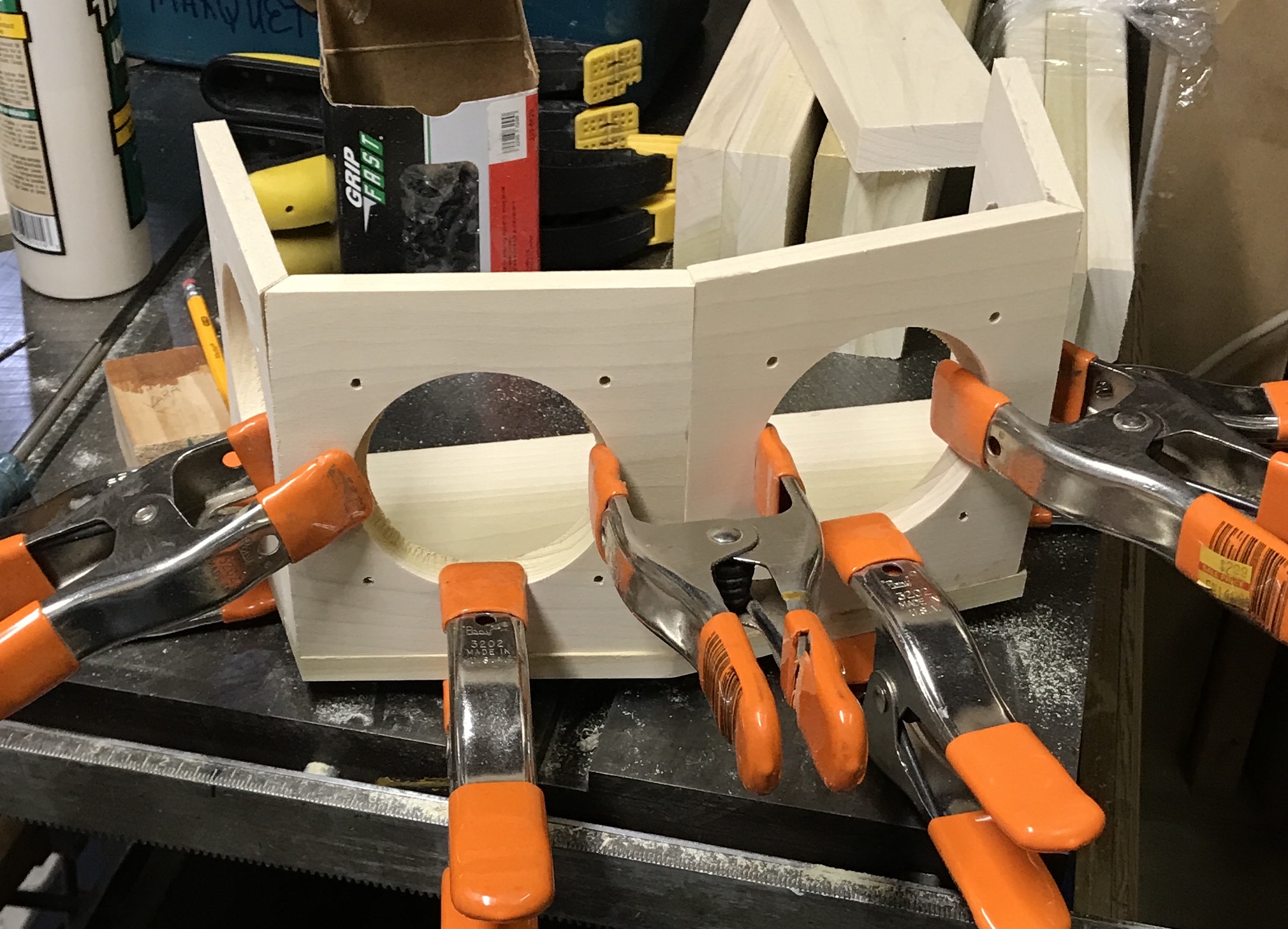
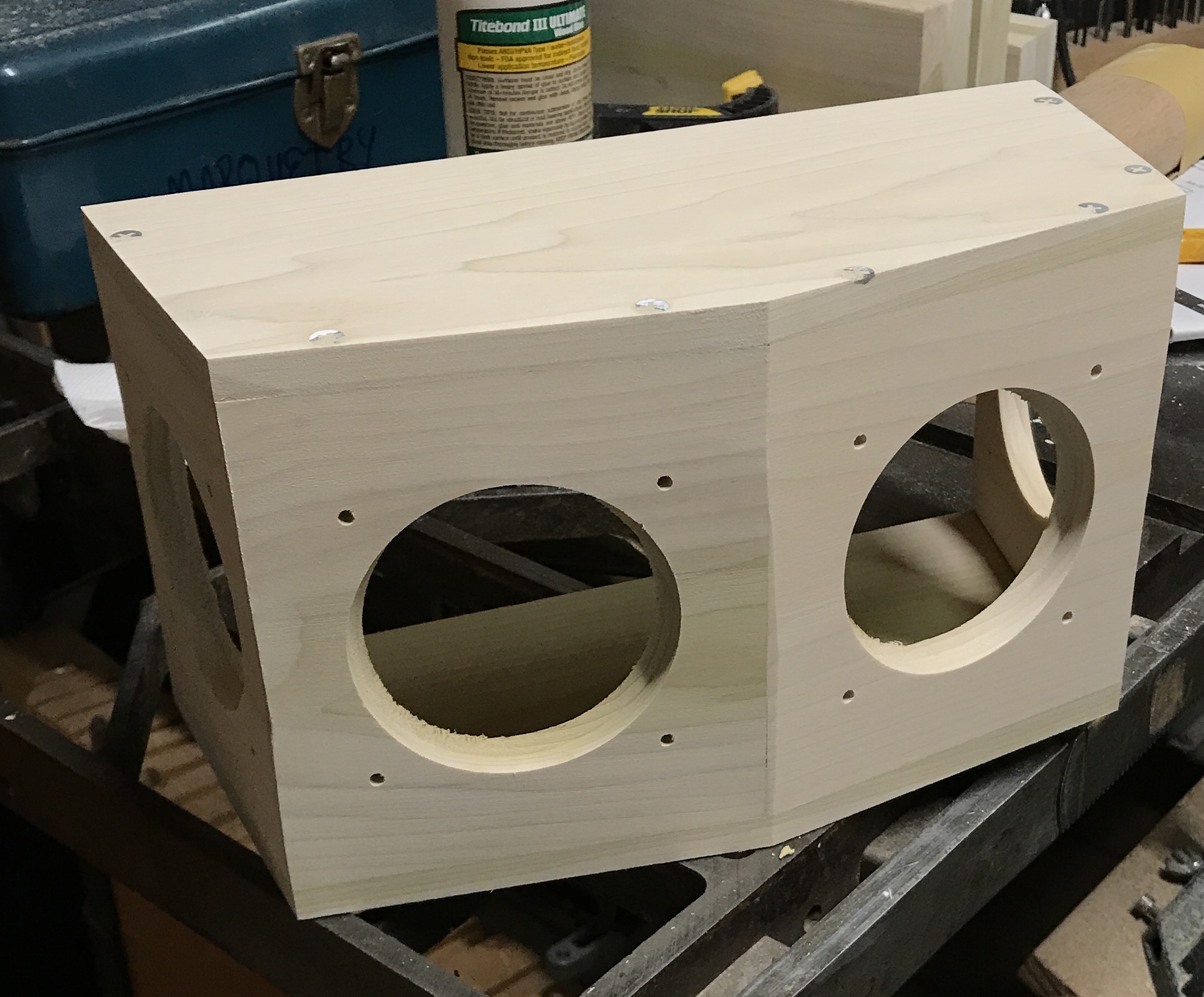
Holes were marked from the speaker to the faces. These were drilled for #6 X 5/8" wood screws. The holes were counter sunk. After playing with the faces and the bottom of the box a plan was devised for gluing the top, bottom, and four faces together. One face's location on the bottom was marked. It was glued, clamped with a pinch screw and screwed in place with two #6 X 1 1/4" drywall screws. The remaining three faces were similarly glued and screwed. Pinch clamps were also used between the faces. The photo shows the clamped faces. Glue was spread on the tops of face edges and the top was put on again with two screws per face.
The clamps were removed. The photo below shows the box at this stage. All of the gaps were filled with wood putty. The screw heads were also covered with wood putty. After drying the all external surfaces were sanded on the belt sander. This produced the box in its final shape. It was then sanded by hand with 220 grit paper. The second photo below shows the sanded box.
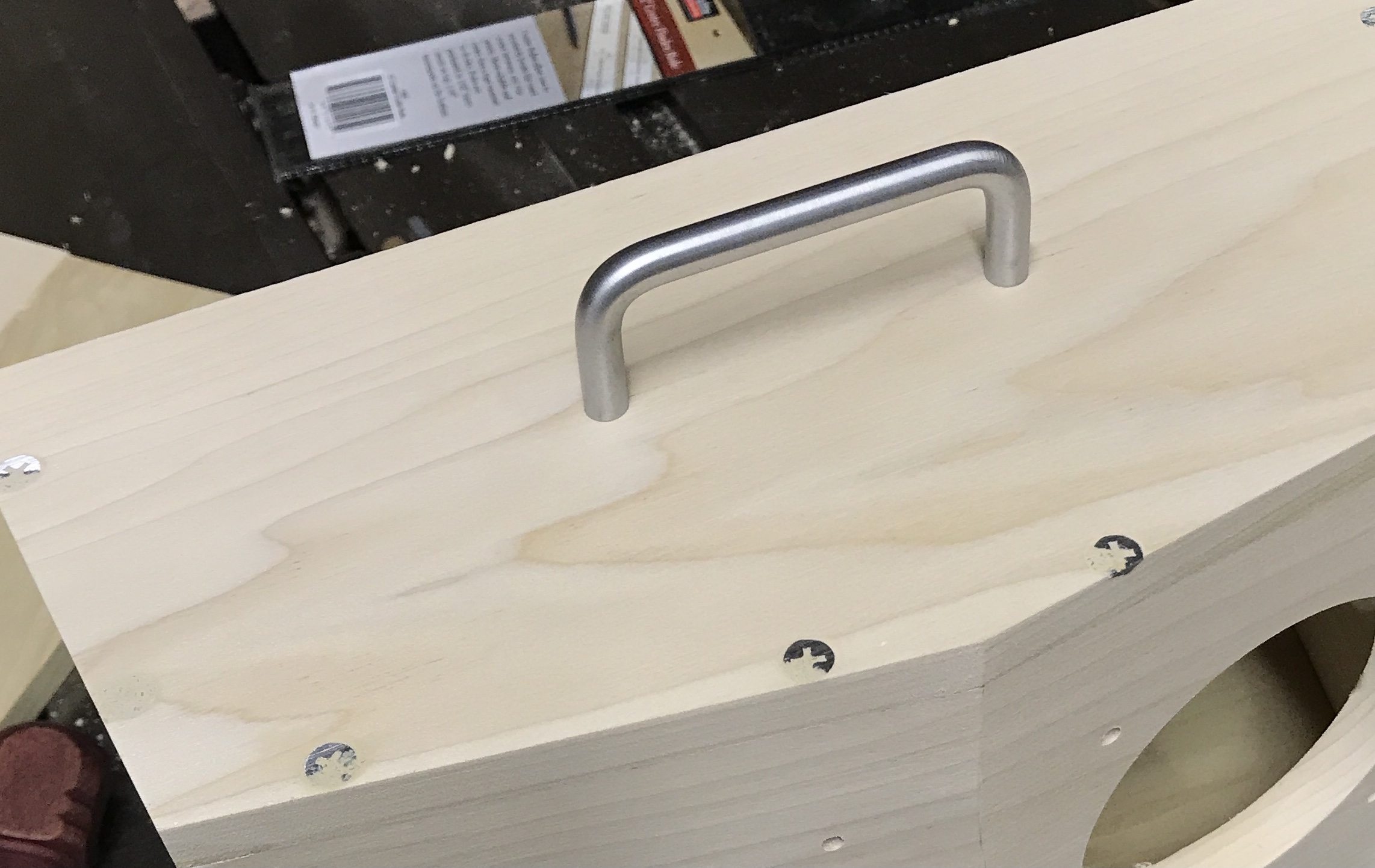
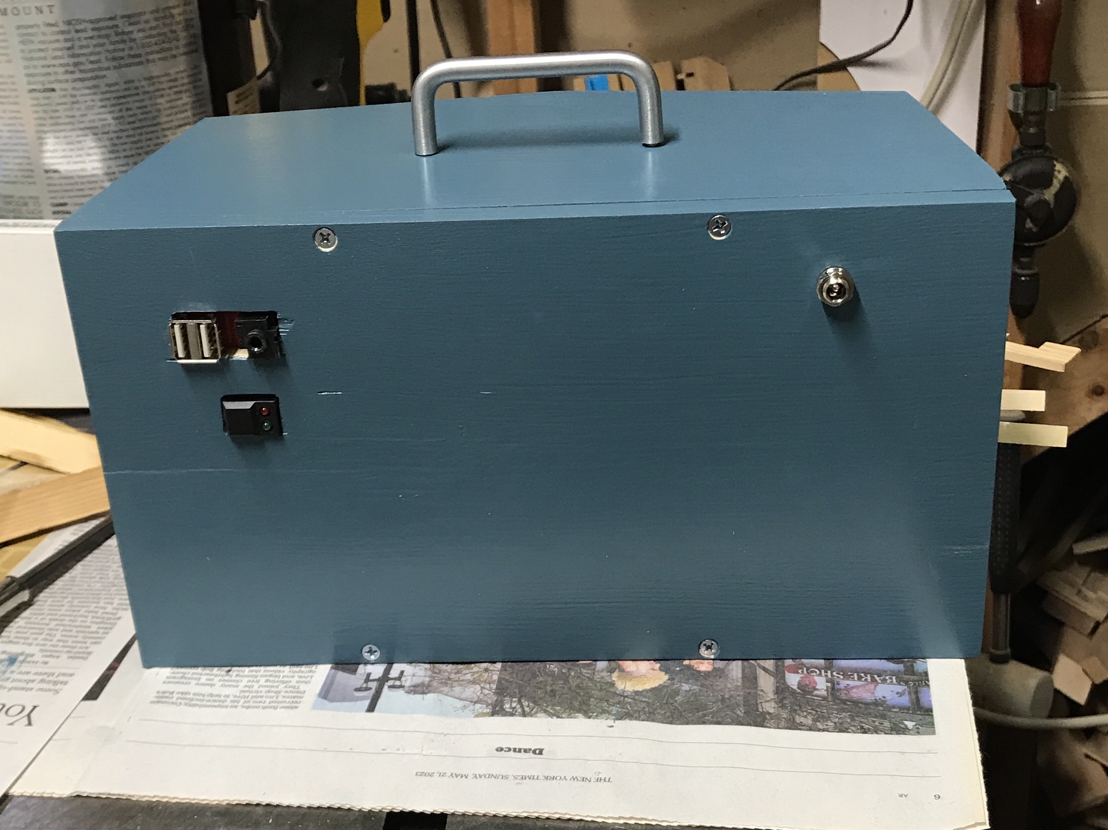
Marked and drilled the top for a 3" long handle. A short or right angle screwdriver is needed to attach the handle. A short screwdriver was located and the handle attached as seen below. The back did not fit as one box side was not square. A corner of the box was sanded on the belt sander removing about 1/8" of material. The back now fits well. It was drilled for four screws with mating holes in the top and bottom of the box.
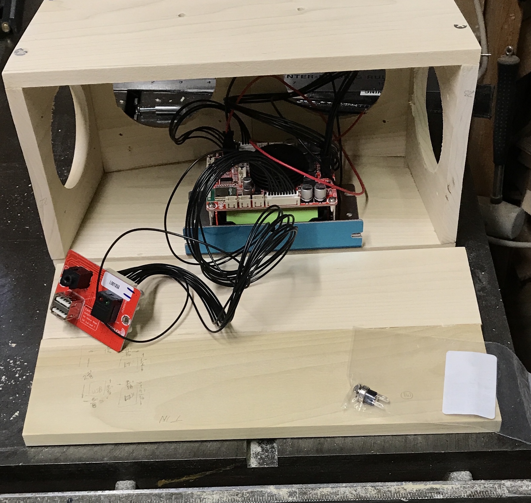
Ryan assembled most of the electronics last evening. The back does not sit flat on the box. One side seems square, but the other side is not. One corner of the box needs to be sanded. The location of the L-bracket on the bottom of the box was determined. A rectangular board with the USB input, lights, and Aux input was located on the back. It will be mounted on the inside of the back with the three rectangular connectors sticking through. In addition the power in connector for charging the batteries was located. The power in connector is a round connector. It is 0.345" in diameter with a 1/8" deep countersink, 0.428". The three connector dimensions are: USB-9/16" X 5/8", Aux-9/16" X 9/16", and lights-1/2" X 11/16". The photo shows the planned location for the L-bracket with batteries and amp, as well as the location of the connector board and the bagged power inlet.
The location of the connector board was carefully mapped out and the locations of each connector was measured and marked. The drill press was used to drill a 1/2" hole in each of the connector locations. A 9/16" drill would have been better for two of the connectors, but none was to be found. The holes were then squared with a 1/2" chisel. The 3/16" block between two connectors came loose and was removed. Even worse was a 2" long tearout on the lights connector. It had to be glued back in place as seen below.
The box sans back was painted the same blue as the Adirondack chairs. The back will be painted when all holes fit connectors. The hole for the power connector was drilled. It was drilled first with an S drill and then countersunk 1/8" with a 27/64" drill. The connector was a perfect tight fit.
The rectangular holes were enlarged as needed with a rasp and sandpaper. When the connectors fit the outside face and edges of the back were sanded to 220 grit. The back was then painted. The box is now rough as the water based paint raised the grain. I plan to sand and repaint after this first coat has completely dried (6 hrs). This was done and the box now looks and feels great. Time to assemble when my course on resawn veneered boxes is over.
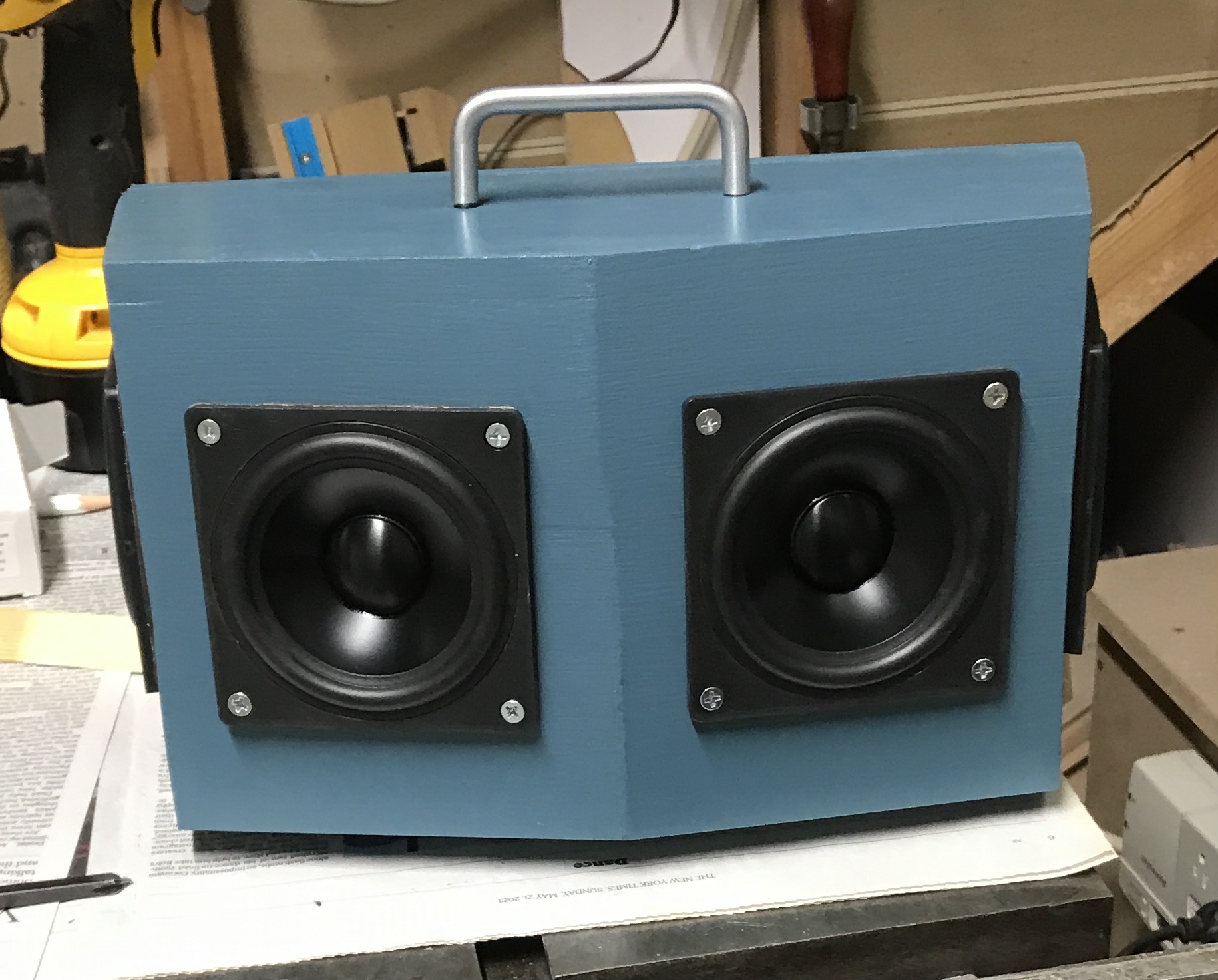
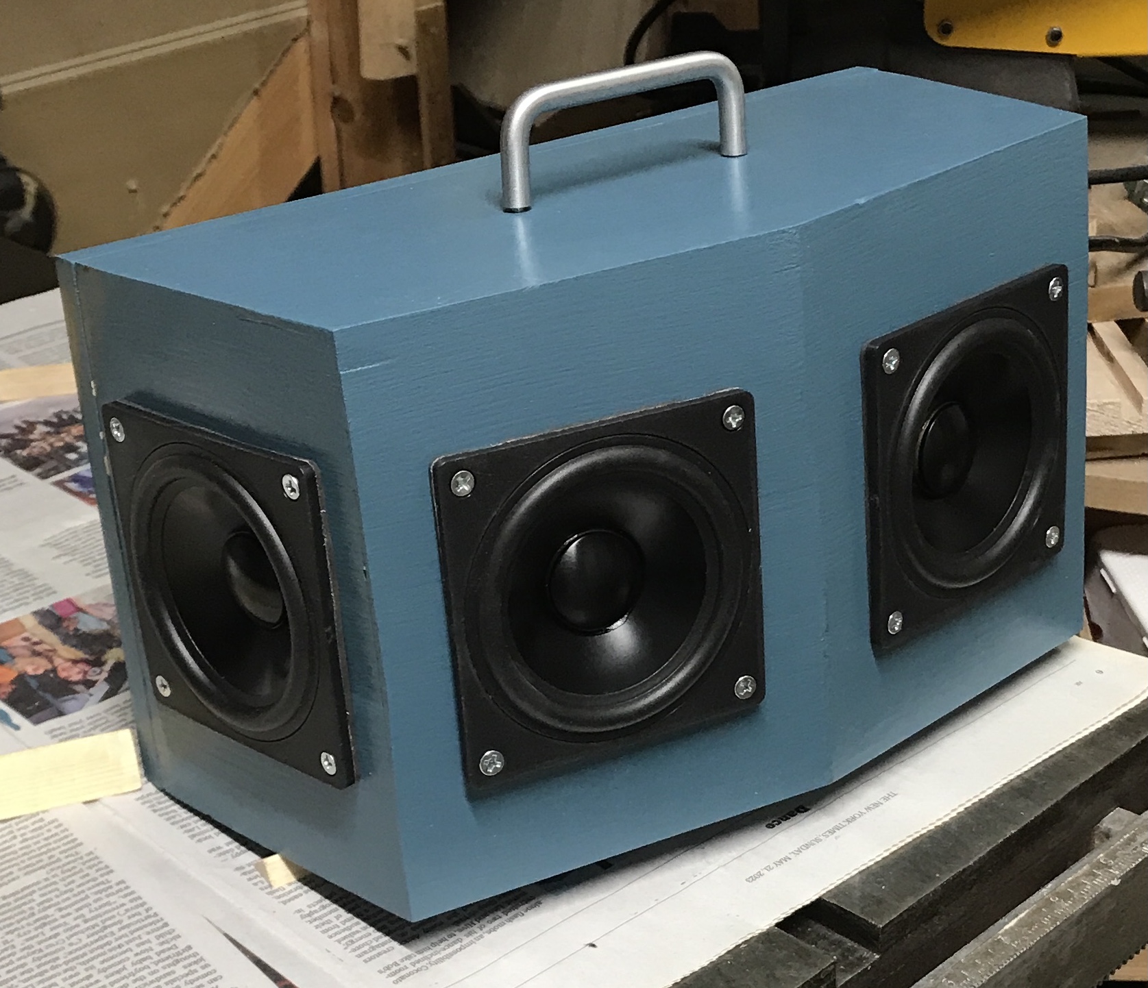
Two screw holes were marked on the bottom for the L-bracket that holds the battery and amplifier. They were drilled with the right angle drilling adapter using a 1/16" drill bit. (The drill had to be almost completely buried in the chuck for the adapter to fit. The 3/8" sticking out was perfect.) The bracket was screwed in place using two #4 X 1/2" wood screws. The input/output board was also screwed to the back with two of the same screws. The charging adapter was pushed into its socket. (It probably needs to be glued in place.) The three photos below show the completed box.
Later in the afternoon Ryan completed the electronics and Rhea hooked her phone up by blue tooth and was thrilled with the result.